 BendPak Mexico
 BendPak Canada
 BendPak Australia
 BendPak UK
 BendPak South Africa
 BendPak UAE
Concrete Slab Requirements
BendPak strongly recommends consulting a Concrete Specialist early in your planning process for Lift installations. The recommendations presented in
this document are generic in nature and cannot cover all situations. A Concrete Specialist will adjust these recommendations to account for national,
state, and local building codes as well as local weather conditions, soil composition, base preparation, load bearing, seismic requirements, and any
other structural concerns that may arise.
Existing concrete floors should be test drilled to verify minimum floor thickness and to confirm building drawings. A core sample should be obtained and tested to verify minimum floor compressive strength. When investigating floor properties, consult building drawings to verify proper floor reinforcement.
- DO NOT install any BendPak lift on any surface other than concrete, conforming to the minimum compressive strength, aging, reinforcement, and thickness stated in the table above. ALL BENDPAK LIFTS MUST BE INSTALLED ON CONCRETE ONLY.
- DO NOT install any BendPak lift on expansion seams or on cracked or defective concrete. All 3/4 inch diameter anchors must be a minimum of 6 inches away from any expansion seams, control joints or other inconsistencies in the concrete.
- All anchors must be a minimum of 6" away from any expansion seams, control joints or other inconsistencies in the concrete. Refer to anchor manufacturer specifications for specific information concerning edge distances and bolt to bolt distance requirements.
- NEVER install a BendPak lift on hand mixed concrete.
- DO NOT install any BendPak lift on a secondary floor level or on any ground floor with a basement beneath without written authorization from the building architect and prior consultation and approval from BendPak.
Click to Open and Download Concrete Slab Requirements (pdf)
Concrete Slab Requirements
Download Concrete Slab Requirements (pdf)
Pre-Existing Minimum Floor Requirements:
| TWO‐POST MODELS | MIN. THICKNESS | MIN. COMP. STRENGTH | REINFORCEMENT | REBAR SPACING |
| GP‐7 SERIES MODELS | 4‐1/4" | 3000 PSI / 28 Day Aging | #6 Rebar | 12 in |
| XPR‐9 SERIES MODELS | 4‐1/4" | 3000 PSI / 28 Day Aging | #6 Rebar | 12 in |
| XPR‐10 SERIES MODELS | 4‐1/4" | 3000 PSI / 28 Day Aging | #6 Rebar | 12 in |
| XPR‐12 SERIES MODELS | 6 1/2" | 3000 PSI / 28 Day Aging | #6 Rebar | 10 in |
| XPR‐15 SERIES MODELS | 8" | 3000 PSI / 28 Day Aging | #6 Rebar | 10 in |
| XPR‐18 SERIES MODELS | 8" | 3000 PSI / 28 Day Aging | #6 Rebar | 10 in |
| 4‐POST LIFTS | MIN. THICKNESS | MIN COMP. STRENGTH | REINFORCEMENT | REBAR SPACING |
| HD‐7 SERIES MODELS | 4‐1/4" | 3000 PSI / 28 Day Aging | ACI Temp Only* | ACI Temp Only* |
| HD‐9 SERIES MODELS | 4‐1/4" | 3000 PSI / 28 Day Aging | ACI Temp Only* | ACI Temp Only* |
| GP‐9 SERIES MODELS | 4‐1/4" | 3000 PSI / 28 Day Aging | ACI Temp Only* | ACI Temp Only* |
| PL‐6K SERIES MODELS | 4‐1/4" | 3000 PSI / 28 Day Aging | ACI Temp Only* | ACI Temp Only* |
| HDS‐14 SERIES MODELS | 4‐1/4" | 3000 PSI / 28 Day Aging | ACI Temp Only* | ACI Temp Only* |
| HDS‐18 SERIES MODELS | 4‐1/4" | 3000 PSI / 28 Day Aging | ACI Temp Only* | ACI Temp Only* |
| HDS‐27 SERIES MODELS | 4‐1/4" | 3000 PSI / 28 Day Aging | ACI Temp Only* | ACI Temp Only* |
| HDSO‐14 SERIES MODELS | 4‐1/4" | 3000 PSI / 28 Day Aging | #6 Rebar | 12 in |
| HD-973P | 6-1/2" | 3000 PSI / 28 Day Aging | ACI Temp Only* | ACI Temp Only* |
| HDS-35 SERIES MODELS | 6-1/2" | 3000 PSI / 28 Day Aging | ACI Temp Only* | ACI Temp Only* |
| HDS-40 SERIES MODELS | 6-1/2" | 3000 PSI / 28 Day Aging | ACI Temp Only* | ACI Temp Only* |
*The floor must be properly aged to American Concrete Institute specifications. The floor does not require reinforcement, but a minimum of wire mesh is recommended.
Existing concrete floors should be test drilled to verify minimum floor thickness and to confirm building drawings. A core sample should be obtained and tested to verify minimum floor compressive strength. When investigating floor properties, consult building drawings to verify proper floor reinforcement. All 2‐post lifts require a continuous single slab. Spanning expansion seams or positioning posts on separate slabs is not acceptable.
- DO NOT install any BendPak lift on any surface other than concrete, conforming to the minimum compressive strength, aging, reinforcement, and thickness stated in the table above. ALL BENDPAK LIFTS MUST BE INSTALLED ON CONCRETE ONLY.
- DO NOT install any BendPak lift on expansion seams or on cracked or defective concrete. All 3/4 inch diameter anchors must be a minimum of 6 inches away from any expansion seams, control joints or other inconsistencies in the concrete.
- All anchors must be a minimum of 6" away from any expansion seams, control joints or other inconsistencies in the concrete. Refer to anchor manufacturer specifications for specific information concerning edge distances and bolt to bolt distance requirements.
- NEVER install a BendPak lift on hand mixed concrete.
- DO NOT install any BendPak lift on a secondary floor level or on any ground floor with a basement beneath without written authorization from the building architect and prior consultation and approval from BendPak.
- If the floor does not meet these minimum pre‐existing floor requirements, it is suggested to construct a slab as outlined below in New Slab Recommendations. If the location of the lift is in a seismic zone, contact BendPak for seismic slab designs.
New Concrete Slab Recommendations:
The information contained in this appendage supersedes any other information given in the accompanied manual. This information is presented for design recommendations for a new concrete slab in the event that the pre‐existing floor does not meet minimum requirements of the applicable lift type. Please read all instructions below carefully before producing new slab.
NEW CONCRETE SLAB CONCRETE REQUIREMENTS:
| Minimum tensile strength of concrete: | 4,000 PSI |
| Minimum aging of new concrete slab: | 28 days (cure time) |
| Minimum thickness of concrete slab: | See new slab table & figures below |
| Minimum width and length of slab: | See new slab table & figures below |
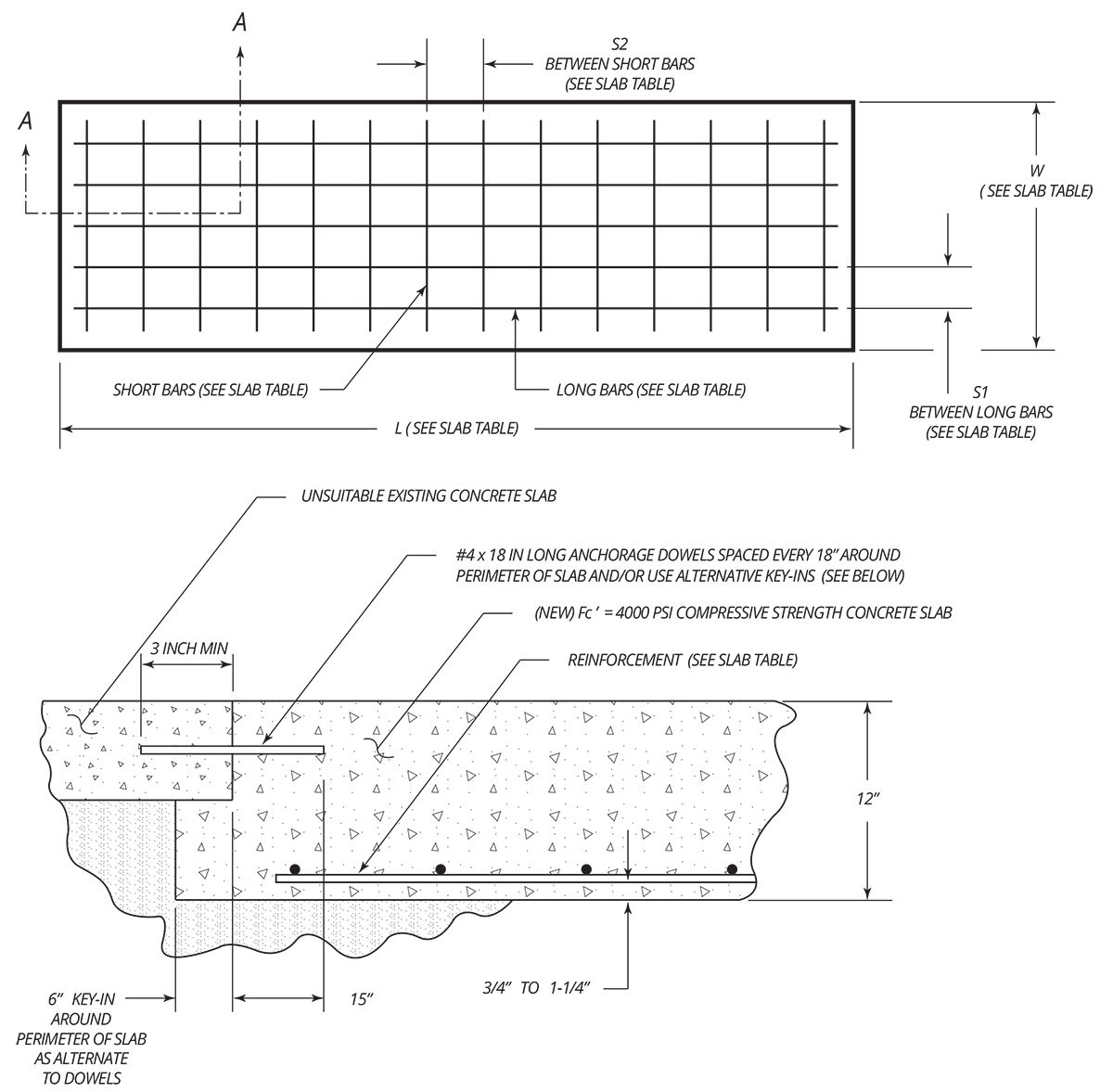
| LIFT MODELS | MIN. SLAB THICKNESS |
W MIN. SLAB WIDTH |
L MIN. SLAB LENGTH |
R REINFORCEMENT SIZE (SEE NOTE 1 & 2) |
S1 & S2 REINFORCEMENT SPACING (SEE NOTE 3) |
D ANCHOR DIAMETER |
I ANCHOR LENGTH |
| GP‐7 SERIES | 12" | 48" Min | 12" Wider Than OA Width of Lift | 8 ‐ #4 ‐ Main Bars 21 ‐ #4 ‐ Temperature Bars |
6" ‐ Long Bars 8" ‐ Short Bars |
3/4" | 5" |
| XPR‐9 SERIES | 12" | 48" Min | 12" Wider Than OA Width of Lift | 8 ‐ #4 ‐ Main Bars 21 ‐ #4 ‐ Temperature Bars |
6" ‐ Long Bars 8" ‐ Short Bars |
3/4" | 5" |
| XPR‐10 SERIES | 12" | 48" Min | 12" Wider Than OA Width of Lift | 8 ‐ #4 ‐ Main Bars 21 ‐ #4 ‐ Temperature Bars |
6" ‐ Long Bars 8" ‐ Short Bars |
3/4" | 5" |
| XPR‐12 SERIES | 12" | 72" Min | 12" Wider Than OA Width of Lift | 12 ‐ #4 ‐ Main Bars 23 ‐ #4 ‐ Temperature Bars |
6" ‐ Long Bars 8" ‐ Short Bars |
3/4" | 7" |
| XPR‐15 SERIES | 12" | 72" Min | 12" Wider Than OA Width of Lift | 12 ‐ #4 ‐ Main Bars 23 ‐ #4 ‐ Temperature Bars |
6" ‐ Long Bars 8" ‐ Short Bars |
3/4" | 7" |
| XPR‐18 SERIES | 12" | 72" Min | 12" Wider Than OA Width of Lift | 12 ‐ #4 ‐ Main Bars 23 ‐ #4 ‐ Temperature Bars |
6" ‐ Long Bars 8" ‐ Short Bars |
3/4" | 7" |
| HD‐7 SERIES | 12" | 24" Min* | 24" Min* | 8 ‐ #4 Bars | 6" ‐ Each Way / Crisscross | 3/4" | 5" |
| HD‐9 SERIES | 12" | 24" Min* | 24" Min* | 8 ‐ #4 Bars | 6" ‐ Each Way / Crisscross | 3/4" | 5" |
| GP‐9 SERIES | 12" | 24" Min* | 24" Min* | 8 ‐ #4 Bars | 6" ‐ Each Way / Crisscross | 3/4" | 5" |
| PL‐6K SERIES | 12" | 24" Min* | 24" Min* | 8 ‐ #4 Bars | 6" ‐ Each Way / Crisscross | 3/4" | 6" |
| HDS‐14 SERIES | 12" | 24" Min* | 24" Min* | 8 ‐ #4 Bars | 6" ‐ Each Way / Crisscross | 3/4" | 5" |
| HDS‐18 SERIES | 12" | 24" Min* | 24" Min* | 8 ‐ #4 Bars | 6" ‐ Each Way / Crisscross | 3/4" | 7" |
| HDS‐27 SERIES | 12" | 48" Min* | 48" Min* | 16 ‐ #4 Bars | 6" ‐ Each Way / Crisscross | 3/4" | 7" |
| HDSO‐14 SERIES | 12" | 48" Min* | 48" Min* | 16 ‐ #4 Bars | 6" ‐ Each Way / Crisscross | 3/4" | 5" |
| HD-973P | 12" | 48" Min* | 48" Min* | 16 ‐ #4 Bars | 6" ‐ Each Way / Crisscross | 3/4" | 5" |
| HDS-35 SERIES | 12" | 48" Min* | 48" Min* | 16 ‐ #4 Bars | 6" ‐ Each Way / Crisscross | 3/4" | 7" |
| HDS-40 SERIES | 12" | 48" Min* | 48" Min* | 16 ‐ #4 Bars | 6" ‐ Each Way / Crisscross | 3/4" | 7" |
*Four separate slabs formed at each post.
Temperature bars are steel rods placed horizontally (longwise) in concrete slabs for prevention of cracks due to temperature changes or drying; placed perpendicular to the main reinforcing rods (short span). Temperature bars are placed at right angles to the main reinforcing bars.
Note 1: Temperature bars are steel rods placed horizontally (longwise) in concrete slabs for prevention of cracks due to temperature changes or drying; placed perpendicular to the main reinforcing rods (short span). Temperature bars are placed at right angles to the main reinforcing bars.
An additional layer of 6 x 6 ‐ 10/10 WWF at mid height of new slab would be advisable in any extremely hot or cold climate to control cracking due to temperature fluctuations and shrinkage. At anchor bolt locations only keep WWF mesh below the elevation of the anchorage to avoid drilling interference with the wire.
Note 2: The main reinforcing and lower temperature steel shall be Grade 60 deformed bars
Note 3: The tolerance on spacing of the bars in each direction shall be the value shown, plus or minus 1 inch. In addition, the number of bars specified in the table must be used.
Note 4: The concrete outline dimensions and the reinforcing shown are for a foundation bed allowable bearing capacity of not less than 2,000 lb. / sq. ft. (1 ton per square foot). Many clays, and most all firm clay, hard clay, sand & clay mixes, dry sands, coarse dry sands, dry sand and silt mixes, sand and gravel mixes, and gravel type soils meet or exceed this allowable bearing capacity. If there is question regarding the foundation bed allowable bearing capacity, a soils testing engineer should be consulted. Situations where the allowable bearing capacity is lower than this value will require special attention.
New concrete slabs must conform to the above stated properties before installation of the lift is deemed acceptable. The new slab must be totally surrounded by an existing asphalt or concrete floor. Certified strength documentation should be obtained from the firm who supplies the concrete mixture at the time of the pour. These new concrete slabs are designed as " s tand alone" and do not take into account the contribution of strength from surrounding concrete. It may be desirable to tie and reinforce the new slab to the pre‐existing surrounding floor. Care should be taken to locate any reinforcement bars away from any anchor positions of the specific lift.
These new concrete slabs do not account for second floor installations or installations in a ground floor with a basement beneath. For this case, the lift should not be installed without written authorization from the building architect.
All 3/4 inch diameter anchors must be a minimum of 6 inches away from any expansion seams, control joints or other inconsistencies in the concrete.
NEVER hand mix your own concrete.
Download Concrete Slab Requirements 2019 (pdf)
NEW CONCRETE SLAB RECOMMENDATIONS
TWO-POST LIFT MODELS
NEW CONCRETE SLAB RECOMMENDATIONS
FOUR-POST LIFT MODELS
